Panoramic Camera
Home | Photography | Projects
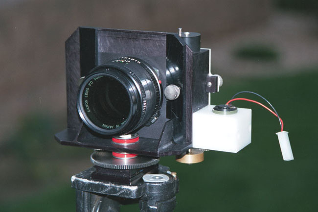
This page gives some information about my homemade panoramic camera, pictured at right. I built the camera in 1997, and have tinkered with it off and on since. This is a rotating panoramic camera, or “Cirkut”-type, named for a brand of camera that was produced in the early 20th century. The Cirkut-type camera rotates as it takes a picture, and can take a complete 360-degree (or more) photo from a single point. (This type of panoramic camera is much different from the “panoramic” mode that many point-n-shoot cameras, including APS cameras, have. The panoramic photos made by those cameras are just enlargements with the top and bottom of the picture cropped off.)
Motivation
I once saw a film about the Cirkut camera in a photography class I took at the local community college. The film didn’t give much detail about how the camera worked, but I thought the photos were cool, and the film made an impression. Shortly after that, I was on a trip to Singapore, and tried to create a panoramic picture of the harbor there by taking nine overlapping shots with a regular 35mm camera, intending to stitch them together later in PhotoShop. That didn’t work very well. I used print film, and even though I locked the camera exposure so that it would be the same for each frame, and had a local photo processor print the photos with all of the same settings, the photos came out dramatically different in apparent color and exposure. After having the photos custom printed so that they approximately matched, I spent several hours trying to stitch them together digitally. There was enough distortion in the photos that I had to adjust each for color, scale it a little, rotate it a little, and position in next to the previous frame. The result was intriguing, but still had some color problems, and took a LOT of time. (This was in 1995, before stitching software was widely available.) I figured there had to be a better way, and started thinking about designing and building a camera. I considered building a swing-lens type camera, for simplicity. In a swing-lens camera, the film is held in a semi-circle behind the lens, and a narrow exposure slit sweeps by the film during the taking of a photo, “painting” the image onto the film. Because the camera body remains stationary, a swing-lens camera is limited to a panorama of less than 180 degrees.
But I wanted to be able to take a complete 360-degree photo, so a rotating type camera was the way to go. This type of camera rotates as it takes a picture, sweeping an exposure slit across the film as it goes. But unlike in a swing-lens camera, the film in a rotating type camera is continuously fed past the lens, with its motion synchronized to the camera rotation so that from the point of view of the lens, the film appears to be stationary. The lens thinks it’s painting the image onto the inside of a cylinder, and the camera body and film are continually getting out of the way of the camera’s view. A rotating type camera can even rotate more than once around, taking a photo of more than 360 degrees, limited only by the film length.
Basic Design Decisions
After choosing 35-mm film because it’s cheap and widely available, the next big decision to make was what lens to use. The lens focal length determines the vertical coverage of each picture, and also the aspect ratio. Based on my experience with the stitched-together Singapore panorama (which was taken with a 105mm lens), I liked the feel of a very wide aspect ratio, and chose a 50mm lens. This gives the same vertical coverage as a “normal” 50mm lens on a 35mm camera, and makes a 360-degree photo about 9 regular frames wide. I considered using an even longer lens, but even with a 50mm lens, only about four complete 360-degree panoramas will fit on a 36-exposure roll of film. Anything longer would use a lot of film, and make photos that might be awkward to work with.
Even so, 50mm is still longer than the lenses on most panoramic cameras that use 35mm film. Because of the limited vertical coverage, I decided to try to include a lens shift feature in the camera. Lens shift is one of the degrees of adjustment available on view cameras, and means that the lens can move up and down vertically, parallel to the film. This has the effect of moving the horizon up and down in the picture, without introducing any perspective distortion. Of course, the lens image circle has to be large enough that the image still covers the film, but that’s not much of a limitation for a panoramic camera. The film is exposed by only a narrow slit behind the lens, so the portion of the film exposed at any one time is much narrower than a full 35mm film frame. Since a normal lens has an image circle large enough to cover a film frame corner-to-corner, that extra coverage provides for the lens to move 10mm up or down from centered on the film. That way, things like city skylines could be taken with the lens shifted up, for a little extra flexibility.
Another consideration for the lens selection was its aperture range. The exposure time in a panoramic camera is a function of the slit width, the rotation speed, and the lens aperture. To keep the design simple, I didn’t want to have to provide an adjustable slit. That left only lens aperture and rotation speed as variables for setting the exposure. The original plan was to have two speeds — corresponding to exposure times of about 1/60th and about 1/2 second, or about 5 stops of exposure range. Five stops isn’t much exposure adjustability, so it was important that the lens have a wide aperture range. I eventually settled on a Canon FD 50/1.4 lens. This lens was available relatively cheaply, and could be adjusted from f/1.4 to f/22, adding another 8 stops of adjustability. A 1/60th second exposure at f/22 would be about right for bright sunlight with 100-speed film, and 1/2 second at f/1.4 would be enough exposure for night shots.
Measuring the Lens
In order for the film synchronization to work correctly, the camera must rotate about the rear nodal point of the lens. The rear nodal point is one focal length away from the film plane when the lens is focused at infinity. However, lens focal lengths are given as nominal values, and the actual focal length of a lens can vary significantly from the nominal number. To design the camera accurately, I needed to know the lens focal length accurately.
To measure the lens focal length, I used a makeshift “nodal slide” — a mechanism for measuring lens focal length. The lens was mounted on a translation stage, with the translation stage sitting on top of a rotation stage. The lens was set for infinity focus. Then I set up an autocollimator looking through the lens and put a bar chart behind the lens. Looking through the autocollimator, I could see the bar chart. If the chart appeared to move as the lens was rotated by the rotation stage, then the lens nodal point was not over the center of rotation. Simply moving the lens the lens back and forth using the translation stage until I found the point where the image in the autocollimator didn’t move with rotation of the lens located the nodal point over the axis of the rotation stage. Measuring the distance from the target to the lens mount gave me the measurement I needed to design the camera body. Measuring the distance from the target to the center of the rotation stage gave the lens focal length, which turned out to be 51.2mm. (If anyone has independently measured a Canon FD 50/1.4 by another method, I’d be interested in comparing measurements.) I also measured a different lens whose focal length I knew accurately to test my measurement method, and it came out pretty close. There was also very little variation between multiple measurements of the same lens.
Of course, once the nodal point is located and the camera is designed around it, it can’t be allowed to move. That means the camera has to be fixed focus. Mine is set to focus at infinity, since I expected to be taking mostly landscapes with it. Some commercial panoramic cameras focus at an intermediate distance and count on depth of field to keep objects out to infinity in focus. That gives those cameras a little better foreground depth of field.
Designing the Camera
Some of the necessary parts came from old junked cameras that camera stores sell for $5 each or so. The lens mount ring came from an old Canon AE-1, and the film takeup reel came from a Pentax camera. I used a 3D CAD system available at my workplace to design the body. The synchronization of the film movement with the camera rotation is accomplished with a set of gears, chosen so that the the film transports past the lens as nearly as possible at the exact speed that the image is painted onto it by the lens, but in the opposite direction. From the point of view of the lens, the film appears to be stationary. The last link in the drive train is a rubber capstan that pulls the film out of the film canister and feeds it past the exposure slit onto the takeup reel. The film takeup reel turns a little faster than the capstan, but is on a slip clutch, so it keeps the film wound snugly but lets the capstan control the speed of film movement past the slit.
The original plan was to have the camera be entirely mechanical, and driven by a hand crank that I would turn. Accordingly, there were two input shafts, one for the “fast” speed and one for the “slow” speed. (Unfortunately, the hand crank idea didn’t work; more about that later.)
I really wanted a viewfinder on the camera. With the shift lens, there is an opportunity to compose the picture a little, and I didn’t want to just guess at the shift setting. The camera has a frosted glass built into the top, and a 45-degree mirror that slides back and forth horizontally between the lens and the film. There wasn’t really room to make the mirror fold up without vignetting the light from the lens substantially. A door on top of the camera swings open to allow viewing through the frosted glass viewfinder. To slide the mirror, you have to manually push a small protuberance under the back of the camera. (And you have to remember to do that!) There’s no prism or other image-rectifying mechanism, so the image in the viewfinder is left/right reversed. It’s upright, though, which is the only important thing, since only vertical coverage of the camera is adjusted while looking through the viewfinder.
Building the Camera
The camera body is machined from a solid chunk of aluminum, so I spent many hours in the machine shop hogging away. Luckily, I had access to a partially-numerically-controlled mill at work. The body was obviously the most time-consuming part, but things like the lens mount board, capstan, film takeup mechanism, and gear clusters took their share of time too. To get the gears, I bough stock gears and modified them by removing hubs and stacking them in pairs to get thin clusters. The “foot” of the camera is a chunk of aluminum that fits into the quick-release socket on my tripod, and also is threaded for a tripod mount. Most of the parts are either black anodized, or made of black plastic.
Using the Camera
The first step in taking a panoramic photo is to find a place that has a good panoramic view. I find that very few spots are interesting for an entire 360-degree view. Most of the photos I take cover around 180 degrees. The horizontal coverage is set by simply pointing the camera a little left of where I want the picture to start, taking the picture, and just shutting off the motor when the the camera has rotated far enough to take in where I want the picture to end. Of course, if I do want to take a complete 360, I have to duck down or walk around behind the camera to avoid being in the picture.
Once a scene is selected, the camera is set up on a tripod and levelled using a bubble level built into the top of the camera. If a panoramic camera is not level, the horizon in the resulting photo will be sinusoidal, rather than level.
Next is setting the lens shift. This means sliding the 45-degree mirror into place and opening the viewfinder door. Two thumbscrews on the front of the camera hold the lens board in place. They’re loosened to allow the adjustment, and then tightened to hold the selected position. It’s important to not only close the viewfinder door, but also to move the 45-degree mirror back out of the way. (Or else you get a black picture!)
There’s no exposure meter, so I carry a regular 35mm camera with me and meter the scene by setting it on shutter priority with the equivalent shutter speed I’m using on the panoramic camera, and then pointing it around and mentally averaging the aperture settings it reads, or noting the aperture setting reading at the most important part of the scene. Of course, the two cameras either have to have the same speed of film in them, or I have to remember to compensate for the difference. (I have ruined pictures in both cameras by forgetting this. If I forget to compensate, then the panoramic picture is incorrectly exposed. If I compensate by setting the ISO setting of the regular camera to match the panoramic camera for metering purposes, then the rest of the roll in the regular camera is incorrectly exposed if I don’t remember to set it back.)
Then it’s just run the motor for the amount of time required to cover the scene.
I mentioned earlier that the hand crank idea didn’t work. I just couldn’t turn it smoothly enough, so I wound up mounting a motor on one end of the camera (in the large white block in the photo above), and driving it from a lithium battery. Fortunately, by chance, it drove the camera at just about the right speed for the fast speed. Unfortunately, it didn’t provide for a slow speed. To compensate a little, I widened the exposure slit from about 0.7mm to about 3mm (about 2 stops), and bought a 2-stop neutral density filter. With the filter in place and at f/22, the exposure was about right for bright sunlight, and I still had about 10 stops of exposure range. A complete 360-degree photo took around 7 to 10 seconds. Actual exposure time for any one point on the film was about 1/15 second.
Experience and Improvements
This setup worked actually pretty well. Most of the photos on the Panoramics page of this website were taken that way, including the nighttime photo of Times Square. But I still wished for a slower exposure mode.
In 2001, just in time for a trip to China, I added a motor speed controller (bought from the internet) that gives me a second, slower speed. Now I have exposure times of about 1/20 second and about 1/2 second, for about an additional 3 or 3.5 stops of exposure range. In the slow mode, a complete 360-degree photo takes about 40 seconds. I put this feature to good use in some of the photos on the China Panoramics page.
One thing that has surprised me is how often I use the lens shift feature in the downward direction. I almost decided to eliminate that capability in the design to save space. I would have still left in the ability to shift the lens UP, as I thought that the lens shift would mostly be useful for city skylines. It turns out, I use the down shift a lot, and I’m glad I left it in. You can see the effect of a strong down shift in the stadium photo and the Niagara Falls photo on the Panoramics page. You can see the effect of a strong up shift in the first two photos of Shanghai on the China Panoramics page.
What Would I do Differently?
If I were to start this project again, knowing what I know now, I would do a few things differently. I would probably choose a shorter lens focal length, after all. The super-wide aspect ratio of my photos is good for some subjects, but I often wish for a little more vertical coverage. One way to deal with this is to take two photos, one with the lens shifted up and one with the lens shifted down, and then scan and stitch the results together into a double-high photo. But sometimes even that isn’t really enough, as you can see from the example on the Hawaii Panoramics page.
I’d start out planning to use a motor drive. Had I intended the camera to be motor-driven from the start, I could have designed a more compact set of gears.
I’d be even more careful about light leakage. I thought I was being careful during the design, but I’ve had to track down a couple of leaks, and haven’t really gotten them all.
I might also try the trick of focusing at a closer distance than infinity — probably the hyperfocal distance for the widest lens aperture.
And I might try a little harder to separate the film motion control from pulling the film out of the canister. As it is, the capstan pulls the film out of the canister and past the slit in one motion. I have a suspicion that the variable resistance of the canister is showing up in the pictures as intermittent blurring in spots. But I’m not sure.
But all in all, I’m pretty pleased with the results.
Some Other Tidbits
People often ask me if I’ve tried to patent my camera, and the answer is no. I don’t think there’s anything patentable in it. A few years ago I visited the British Museum of Science in London, and looked through the photography exhibit for cameras that use this or a similar principle. The oldest one I found was built in 1861. That camera took an extra-wide photo using a translational motion of the film, rather than by rotating the camera, but it does show the basic idea has been around for over 140 years.
Choosing a good subject is important. I’ve proven many times that it’s possible to take boring pictures with a panoramic camera, just as it is with any camera. I find that “busy” scenes work well. I’ve printed a few of these photos on a large printer, making prints up to 8 or 10 feet long. A large print like that can be fascinating to look at.
All of the photos on this site were scanned with an HP PhotoSmart S20 scanner. I don’t know of any other consumer scanner that can scan a strip of film as a single image. The S20 can scan about 5 or 6 frames worth of film in one pass. If I want to scan a complete 360, I have to scan it in two pieces and stitch it together digitally.
Occasionally, people ask if they could get copies of the plans for the camera. I doubt if my drawings would be very useful to anyone else. The camera design is tailored to the parts, materials, and tools I had available, as well as to my own moderate machining skills.
Photos of the Camera Itself
Here are a few photos of the camera, showing various features. As always, you can click on any photo to see a larger version.
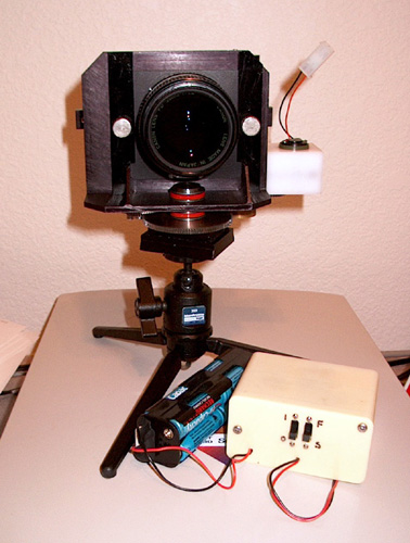
Here’s a picture of the camera from the front, also showing the batteries for the motor drive, and the package for the motor speed controller.
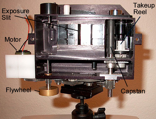
This photo shows the camera from the rear, with the back removed and with no film. The exposure slit is made from two razor blades glued in place (and covered with electrical tape).
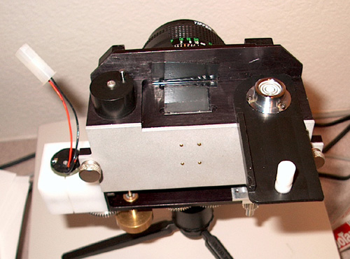
This photo shows the viewfinder door opened. The frosted glass is visible on the top of the camera. The round brass thing at the lower left is a flywheel.
Thanks for visiting!